Creating your own designs for laser cutting can be an exciting endeavor, but navigating the initial steps can feel like piecing together a puzzle with scattered information. This guide aims to provide a clear, beginner-friendly workflow, walking you through the entire process from design to g-code generation, ensuring you have a comprehensive understanding to get started.
The Design Process: Vectorization and G-code
At its core, preparing a design for laser cutting involves two primary components:
The Vectorized Design: This forms the blueprint of your creation, defining the precise paths the laser will follow. These designs are typically saved in vector file formats such as SVG (Scalable Vector Graphics) or DXF (Drawing Exchange Format). While raster images can be used, they are often converted to a vectorized format at some stage, either initially or during g-code generation, to ensure clean, scalable lines.
G-code Generation: This is the translation of your vectorized design into specific instructions for your laser cutter. G-code dictates the laser's movement, speed, and power settings, based on whether you intend to engrave, cut, or score your material.
Choosing Your Design Software
Several software options are available for creating vector designs. Paid, professional-grade tools like Adobe Illustrator, AutoCAD, Fusion 360, and Solidworks CAM offer extensive features. AutoCAD, for instance, is a powerful option often accessible to students through free licenses. However, for hobbyists and those seeking a more accessible entry point, Inkscape stands out as the premier choice. It is a free and open-source vector graphics editor that provides all the essential features needed for laser cutting design.
Generating G-code: From Design to Machine Instructions
Once your vector design is ready, the next step is to generate the g-code that your laser cutter will understand. While some design software might offer limited g-code generation capabilities, dedicated programs are generally preferred for their specialized features.
LightBurn is widely considered the industry standard and the go-to option for many laser users. It is a paid software, but its comprehensive feature set, including design capabilities and advanced control over laser operations, makes it a worthwhile investment for serious users.
For those seeking a free and open-source alternative, LaserGRBL is an excellent choice. It is simpler than LightBurn but provides all the necessary tools for g-code generation. While it might require a bit more manual configuration, its accessibility makes it a fantastic starting point for beginners. Another option, VisiCut, is also available and worth exploring for its functionalities.
For the purpose of this tutorial, we will focus on the powerful combination of Inkscape for design and LaserGRBL for g-code generation.
Designing in Inkscape: Mastering the Workflow
When embarking on your laser cutting design journey in Inkscape, two fundamental concepts are crucial to remember:
- Lasers Work with Paths: Every element in your design needs to be understood by the laser as a path - a defined line or curve that the laser beam will trace.
- Color Dictates Action: Most lasers and their associated software use color to differentiate between cutting, engraving, and scoring operations.
Setting Up Your Document
A highly practical tip when starting your design is to set your Inkscape document's dimensions to match the exact size of the material you plan to cut. This allows for accurate placement of your design elements and provides a clear visual representation of the available space. When you later import this design into LaserGRBL, these dimensions and offsets should be preserved, simplifying the alignment process.
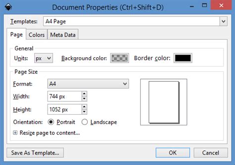
To do this, navigate to File > Document Properties. Within this panel, you can set the Height and Width of your document. It's also advisable to ensure your Display units match your document units (e.g., millimeters or inches) to avoid any potential confusion.
Converting Objects to Paths
The principle that lasers work with paths means that all elements, including text and shapes, must be converted into vector paths. If you intend to fill an area for engraving, this fill must also be composed of paths that the laser can trace.
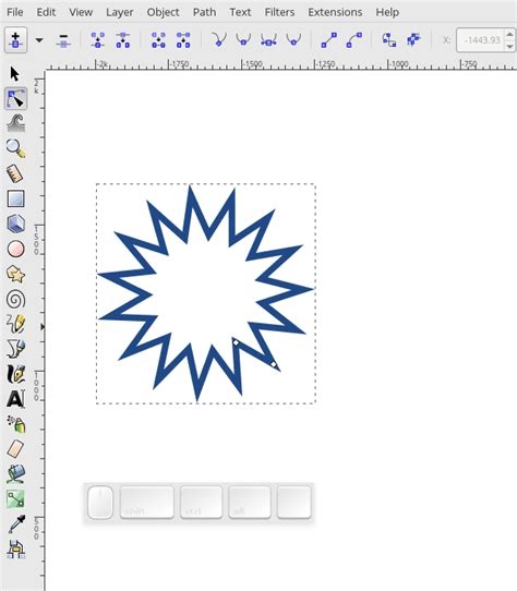
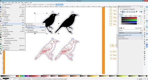
In Inkscape, converting most objects to paths is straightforward. Select the object you wish to convert and use the Object to Path option. This is typically found under the Path menu, or you can use the shortcut Shift + Ctrl + C (Windows/Linux) or Shift + Cmd + C (Mac).
This conversion is essential for elements like text. When you add text in Inkscape, it exists as editable text data. However, for laser cutting, this data needs to be transformed into a series of lines and curves. Similarly, if you draw a rectangle and want it to be engraved, simply filling it with a solid color in Inkscape won't directly translate to an engraved area. Instead, you need to fill that shape with a series of tightly packed paths.
Hatch Fills for Engraving
To achieve a filled engraving effect, the easiest method in Inkscape is to use a hatch fill. This involves creating a pattern of parallel lines within a shape, which the laser will then trace over to engrave the area. Inkscape has a built-in extension for this purpose.
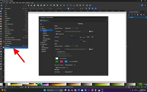
- Install the Hatch Fill Extension: Go to Extensions > Manage Extensions. In the search bar, type "Hatch Fill" and install it if it's not already present.
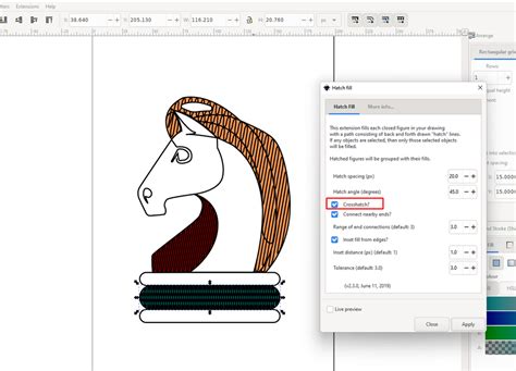
- Apply the Hatch Fill: Select the shape you wish to engrave. Then, go to Extensions > Generate from Path > Hatch Fill.
- Configure Settings: A dialog box will appear. Turn on the Live Preview option to see the effect of your settings in real-time. For a solid engraving, you'll want the hatches to be closely spaced. A spacing of around 0.25mm is often a good starting point, but this can be adjusted based on your material and desired engraving depth. Experiment with the settings until you achieve the look you desire.
- Apply and Close: Once satisfied with the preview, click Apply. You can then close the extension dialog.
This process effectively fills your shape with a series of vector paths, ready for laser engraving.
Understanding Color Mapping for Laser Operations
The way laser cutters interpret your design is heavily influenced by color. While specific color mappings can vary slightly between machines and software, a common and effective scheme is:
- Red: Typically designated for cutting.
- Blue: Often used for scoring (a shallow cut that doesn't go all the way through the material).
- Black: Generally used for engraving.
LaserGRBL offers flexibility by allowing you to parse SVG files based on red, blue, black, and green colors, providing a good range of control. Adopting this color scheme in your Inkscape designs will streamline your workflow significantly, as it allows you to visually distinguish between different operations and easily configure them in LaserGRBL.
Incorporating Images into Your Designs
While Inkscape is primarily a vector editor, it can also handle raster images. If you wish to laser engrave an image, you'll typically need to convert it into a vector format first.
- Import or Paste Image: Bring your image into Inkscape.
- Trace Bitmap: Select the image and go to Path > Trace Bitmap.
- Choose a Method: Within the Trace Bitmap dialog, you have several options. Edge Detection can be useful for finding outlines, while Brightness Cutoff is effective for creating a silhouette or removing a background based on color intensity. Experiment with these settings to achieve the desired outline or shape.
- Convert to Path: After tracing, you will have a vectorized version of your image. You can then convert this output to paths if it isn't already, and combine it with other elements in your design.
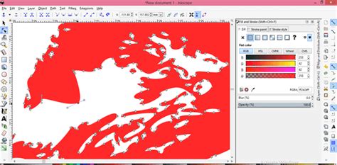
This process allows you to transform photographic or raster-based images into scalable vector shapes that can be cut or engraved by your laser.
A Sample Design in Inkscape
Consider a simple design incorporating different operations. You might have a red outline for cutting the main shape, blue lines for scoring registration marks, and black areas for engraved text or patterns. By assigning these colors in Inkscape, you create a visual representation of the laser's intended actions.
Configuring in LaserGRBL: Bringing Your Design to Life
With your design exported from Inkscape as an SVG file, you can now move to LaserGRBL to prepare the g-code for your laser cutter.
The "Open and Append" Workflow
LaserGRBL operates on an "open and append" principle. You can open your SVG file, and then sequentially append the same or different files. Each time you append a file or a filtered selection from a file, you configure the settings for that specific layer or operation.
For instance, using our sample design:
- Open the SVG: Load your exported SVG file into LaserGRBL.
- Filter and Configure Red Layer: You can then filter the design to show only the red elements (intended for cutting). Apply your cutting speed, power, and other relevant settings for this layer.
- Append and Filter Blue Layer: Next, append the same SVG file again. This time, filter for the blue elements (scoring) and configure the appropriate scoring settings.
- Append and Filter Black Layer: Repeat the process for the black elements (engraving), applying your engraving speed and power settings.
By layering these operations, you construct the complete sequence of actions your laser will perform.
Configuring Cutting and Engraving Settings
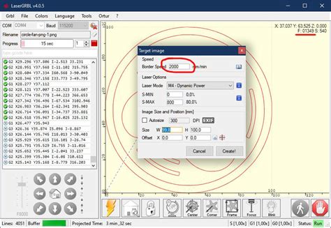
The most critical settings you will configure for each layer are:
- Border Speed: This influences the speed at which the laser moves.
- S-MIN and S-MAX: These parameters often relate to the laser's power output (e.g., PWM duty cycle). S-MIN might represent the minimum power, and S-MAX the maximum power.
- Filter: This refers to the color filtering you apply to select specific elements from your SVG.
The precise values for these settings (speed, S-MIN, S-MAX) are highly dependent on several factors:
- Material Type: Different materials (wood, acrylic, paper, etc.) require vastly different power and speed settings.
- Material Thickness: Thicker materials necessitate more power and potentially slower speeds.
- Laser Cutter Specifications: The wattage and capabilities of your specific laser cutter are paramount.
- Desired Outcome: The depth of engraving or cut required will influence these settings.
It is essential to consult the documentation or recommended settings for your specific laser cutter and material. Experimentation is often key to achieving perfect results.
Preparing Text for Laser Cutting in Inkscape
A crucial aspect of designing with text for laser cutting is ensuring that the text is properly converted into vector shapes that the laser can interpret. Most manufacturing and laser cutting software cannot directly "read" text boxes from a design file. Therefore, text must be converted to vector shapes and paths.
Converting Text to Paths
As mentioned earlier, the Object to Path function is your primary tool here. Once you have typed your text in Inkscape, select it and apply this conversion. Your text is now a vector path, ready for laser processing. However, it's important to note that from this point forward, it can no longer be edited as text.
Bridging for Reversed Cut-out Text
When creating designs where text is "cut out" from a larger shape (e.g., for signage), you need to consider letters with internal cut-outs like 'O', 'P', 'B', or 'A'. If you simply cut these letters out, the internal pieces (the centers of the 'O', 'P', etc.) would fall out. To prevent this, you need to add "bridges" or "webs" to these letters.
Adding Bridges: A Step-by-Step Approach
- Enable Snapping: Ensure snapping is enabled in Inkscape to accurately position your bridges.
- Draw a Bridge Shape: Use the Rectangle tool (F4) to draw a small rectangle where you want the bridge to connect parts of a letter.
- Path Division: Select both the letter and the bridge rectangle. Go to the Path menu and select Division (
Ctrl + /orCmd + /). This will cut the letter along the path of the rectangle, effectively integrating the bridge. - Create the Reverse Cut-out Shape: For the overall shape from which the text will be cut, you'll typically use a simple rectangle. Ensure this rectangle is positioned underneath your letters.
- Path Exclusion: Select both the letters (with their bridges) and the background rectangle. Go to the Path menu and select Exclusion (
Ctrl + ^orCmd + ^). This operation will cut the shape of your letters out of the background rectangle, leaving the desired reverse cut-out effect.
When creating bridges, be mindful of the minimum geometry required for cutting. Your bridges should be thick enough to be structurally sound and to meet the minimum bridging/webbing thickness recommended for your chosen material. Many fonts can accommodate bridging without compromising the aesthetic integrity of the design.
Font Selection for Laser Cutting
The choice of font can significantly impact the success of your laser-cut text, especially when dealing with intricate designs or reverse cut-outs. Some fonts are more robust and lend themselves better to laser cutting due to their stroke thickness and letterform structure. While this tutorial focuses on the technical process, exploring articles and resources that suggest suitable fonts for laser cutting can be highly beneficial.
Finalizing Your Laser Cutting Project
The process of designing for laser cutting involves careful preparation and understanding of how your chosen software and machine interpret your designs. Inkscape provides a powerful and accessible platform for creating the vectorized artwork, while tools like LaserGRBL translate that artwork into machine-readable instructions. By mastering the concepts of vector paths, color mapping, and specific techniques like hatch fills and text bridging, you can confidently bring your creative visions to life through laser cutting. Remember to always consult your laser cutter's specific guidelines and experiment with settings to achieve the best results for your materials and projects.