Inkscape is a powerful and versatile open-source vector graphics editor that empowers users to create a wide array of visual content, from intricate logos and detailed diagrams to flowcharts, schematics, and even artistic illustrations. Unlike raster image editors such as GIMP, which manipulate pixel-based images, Inkscape operates on the principle of vector graphics. This fundamental difference means that images created in Inkscape are resolution-independent, allowing them to be scaled infinitely without any loss of quality. This makes Inkscape an indispensable tool for researchers, designers, educators, and hobbyists alike, enabling them to present complex information in a clear and visually appealing manner.
Understanding the Fundamentals: Vectors vs. Rasters
The distinction between vector and raster graphics is crucial for understanding the capabilities of software like Inkscape. Raster images, often referred to as bitmap images, are composed of a grid of individual pixels. When you zoom in on a raster image, you eventually start to see these individual squares, leading to a pixelated or blurry appearance. Examples of raster formats include JPEG, PNG, and GIF.
Vector graphics, on the other hand, are defined by mathematical equations that describe points, lines, curves, and shapes. These mathematical descriptions allow vector images to be scaled to any size without compromising their sharpness or detail. When you scale a vector image, the software simply recalculates the mathematical formulas, ensuring a crisp and clear output at any resolution. This inherent scalability is what makes Inkscape ideal for creating graphics that need to be used across various media, from small web icons to large-format print materials.
Getting Started with Inkscape: Your First Schematic
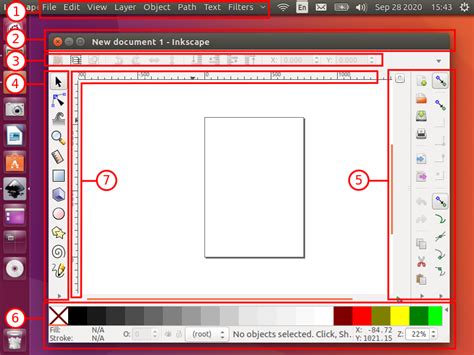
For those new to Inkscape, the interface might seem a bit daunting at first. However, with a systematic approach, its functionalities become readily accessible. Let's embark on a practical exercise to create a schematic, similar to what researchers might use to illustrate complex results. We will aim to create a simplified representation of an embryo, explaining its main structures.
The Inkscape window typically presents a canvas, a toolbox on the left, and various panels for customization, often including fill and stroke options, as well as alignment tools. If you find yourself missing certain panels, you can usually access them through the "View" menu, under "Show/Hide."
Creating Basic Shapes: Circles for the Embryo
To begin, let's create a circle to represent the outer layer of our embryo.
- Select the "Circle" tool: This tool is located in the toolbox on the left side of the Inkscape window.
- Draw the circle: Click and drag on the canvas. To ensure you create a perfect circle rather than an ellipse, hold down the Ctrl key while dragging.
- Adjust Fill and Stroke: After creating your circle, right-click on it and navigate to "Fill and Stroke." This panel allows you to define the object's color, stroke width, and other visual properties. For our embryo, let's create two concentric circles. The outer circle can represent the "zona pellucida," a glycoprotein layer. The inner circle can represent the "trophectoderm," a layer of cells that will develop into embryonic annexes.
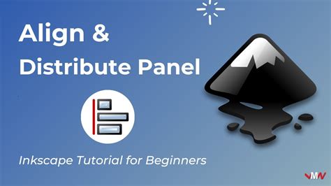
Precise Placement: Aligning Objects
To ensure our two circles are perfectly centered, we can utilize the "Align and Distribute" tool. If this panel is not visible, you can enable it via View > Show/Hide > Commands bar, and then access it through the dedicated icon.
- Select both circles: Click on one circle, then hold down the Shift key and click on the second circle.
- Use the Align and Distribute tool: In the "Align and Distribute" panel, under the "Align" tab, you'll find options to align objects relative to each other. To center them, you would typically use the options for aligning on the vertical and horizontal axes.
Crafting Custom Shapes: The Inner Cell Mass
The main part of our embryo at this stage is the "inner cell mass," which is typically depicted as a darker, more irregular region within the inner circle. While Inkscape excels at creating standard shapes, it also provides powerful tools for modifying them into custom forms.
- Start with a standard shape: Create another circle, approximately two-thirds the size of the inner circle. You can use a dark gray color for its fill, similar to the stroke color of the previous circle.
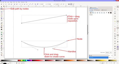
- Convert to Path: To edit the individual nodes of a shape, you first need to convert it into a path. Select your new circle and go to Path > Object to Path.
- Edit Nodes: Now, select the "Edit path by nodes" tool (often represented by a cursor icon). Click on your object again. You will now see nodes (small squares or diamonds) at various points along the circle's outline.
- Manipulate Nodes: With the "Edit path by nodes" tool active, click and drag individual nodes. For instance, to create a slightly flattened appearance for the inner cell mass, you might drag the top node downwards slightly. Holding down the Ctrl key while dragging can constrain the movement to orthogonal directions, ensuring cleaner edits. Zooming in using Ctrl and the mouse scroll wheel is highly recommended for precise adjustments.
Introduction To Nodes and Paths | Inkscape Beginner Tutorial
Positioning and Resizing Objects
Once you've shaped the inner cell mass, you'll need to place it correctly within the other circles.
- Use the "Select and Transform Objects" tool: This is usually the top-left tool in the toolbox.
- Move the object: Click and drag the inner cell mass to its desired position.
- Scale the object: When the object is selected, a bounding box with arrows will appear around it. Use these arrows to resize the inner cell mass to fit appropriately within the inner circle.
- Rotate the object: Clicking on a selected object a second time will reveal rotation handles. You can then use the curved arrow in the corner of the bounding box to rotate the object. Fine-tuning the shape by editing nodes again can help it fit more organically with the surrounding structures.
Adding Labels and Annotations
Clear labeling is essential for any schematic. Inkscape's "Text" tool makes this straightforward.
- Select the "Text" tool: This is typically represented by an "A" icon.
- Add text: Click on a blank area of the canvas and type the names of the structures you've created (e.g., "Zona Pellucida," "Trophectoderm," "Inner Cell Mass").
- Create connecting lines: To visually link the text labels to their corresponding structures, use the "Draw bezier curves and straight lines" tool (often a pencil icon).
- Select the tool.
- Click where you want a line to start (e.g., on the border of the "Zona Pellucida").
- Click again for subsequent nodes or to create bends in the line.
- Right-click when you have finished drawing the line.
With these steps, you will have created a clear and informative schematic of an embryo, ready for use in presentations or publications.
Saving and Exporting Your Work
Inkscape offers flexible options for saving and exporting your creations.
Saving as an Editable Vector File
To preserve the ability to edit your graphic at any time, save your work in Inkscape's native format.
- Go to File > Save As.
- Choose "Inkscape SVG" from the file type dropdown menu. This format retains all the vector information, allowing you to reopen and modify the file in Inkscape later.
Exporting as a Raster Image
If you need to use your graphic in applications that do not support vector formats, or for web use, you can export it as a raster image.
- Select all objects that you want to include in the export.
- Go to File > Export Bitmap.
- In the export dialog, you can specify the area to export (e.g., "Selection"), the desired resolution (DPI), and the filename.
- Click "Export" to save the raster image (commonly as a PNG file).
Advanced Techniques and Resources
While this tutorial covers the basics of creating a simple schematic, Inkscape offers a vast array of advanced features. Many users find that combining different tools and techniques can lead to highly sophisticated results.
Exploring Beyond the Basics
For those who have grasped the fundamentals, further exploration is highly encouraged. The "Inkscape Beginner's Guide," published by Packt Publishing and authored by Bethany Hiitola, is a valuable resource for those who prefer book-based learning over video tutorials, offering a structured approach to mastering Inkscape's capabilities. It's worth checking if this book came with accompanying digital guides, which can often be found on a PC after installation.
The Inkscape community is also a rich source of knowledge. Numerous tutorials, both text-based and video, are available online. Websites such as simarilius.wordpress.com host a collection of Inkscape tutorials, some of which might address specific needs like creating irregular gradients or custom markers.
Customizing Inkscape: Resetting to Defaults
Sometimes, accidental changes to settings can lead to unexpected behavior. For instance, if your "Fill and Stroke" settings are altered, creating a circle might result in an unusual shape, like a "backwards Pack Man."
To reset Inkscape to its default settings:
- Close Inkscape.
- Locate the Inkscape configuration folder. The location varies by operating system:
- Windows:
%APPDATA%\inkscape\ - macOS:
~/.config/inkscape/ - Linux:
~/.config/inkscape/
- Windows:
- Within this folder, find and delete the
preferences.xmlfile. - Restart Inkscape. This will recreate the
preferences.xmlfile with the default settings.
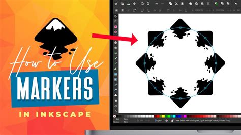
Working with Markers and Gradients
Inkscape's capabilities extend to more complex features like custom markers and gradients. For instance, the ability to import marker definitions from other files or apply gradients within markers can significantly enhance the visual appeal and informational density of your graphics. While some users have reported difficulties with gradients in markers, it's known to work in certain development versions (SVN) of Inkscape. Experimentation and exploring community forums can often yield solutions to such advanced challenges.
Learning Resources and Community Support
The preference for learning resources varies greatly among individuals. While some find video tutorials on platforms like YouTube to be the most effective, others, like those who prefer books, find the structured approach of written guides more conducive to learning. The frustration of constantly pausing and rewinding videos can be a significant drawback for some.
For those seeking specific types of tutorials, such as creating logos with specific color schemes (e.g., a black and gold logo for "Denali Designs"), searching for text-based tutorials with image steps can be beneficial. These often break down complex processes into manageable, visual stages.
Newcomers to Inkscape, especially those using it in conjunction with hardware like cutter/plotters, can benefit from starting with the earliest available tutorials and progressively working through more advanced ones. When encountering issues, such as the checkerboard tutorial problem described by one user where objects combine unexpectedly after an alignment step, it's crucial to identify the exact version of Inkscape being used and to provide specific details about the steps leading to the problem. Often, subtle differences in the "Relative to" setting within the "Align and Distribute" panel can be the source of such discrepancies.
The ongoing development of Inkscape means that features and functionalities are constantly being refined. Staying updated with community discussions and actively seeking out new tutorials can ensure that users are leveraging the full potential of this powerful vector graphics editor.