Inkscape is a powerful, open-source software for creating and editing vector graphics. This makes it an exceptionally useful tool for designing parts intended for laser cutting and engraving. Its ability to generate precise 2D design files, suitable for both simple and complex geometries, combined with its free accessibility, positions Inkscape as a leading choice for hobbyists and professionals alike. While Inkscape may present a steeper learning curve for those new to vector design software, this tutorial aims to demystify the process, focusing on preparing text for laser cutting.
The Necessity of Vector Paths for Laser Cutting
A fundamental challenge when preparing designs for laser cutting is that most manufacturing and laser cutting software cannot directly interpret text boxes from a design file. To ensure precise cutting, text must be converted into vector shapes and paths. This conversion is a critical step, as it dictates how the laser will trace the outlines of your design. Failing to perform this conversion can lead to errors in the cutting process, resulting in incomplete or incorrect parts.
Converting Text to Vector Paths
The process of converting text into editable vector paths is straightforward within Inkscape. Once your text is created using the text tool, it needs to be transformed into a format that the laser cutter can understand. This is achieved by converting the text object into a path.
- Select your text: Use the selection tool to highlight the text you wish to convert.
- Convert to Path: Navigate to the
Pathmenu and selectObject to Path(or use the keyboard shortcutShift + Ctrl + C).
Upon completing this action, your text is no longer editable as text. It has become a series of interconnected vector paths. If your intention is to cut each letter individually as a standalone element, this converted text is now ready for that purpose. However, if the goal is to create signage where letters are part of a larger structure, further considerations come into play.
Preparing Text for Signage and Reverse Cut-outs
When designing text intended to be part of a larger structure, such as for signage that will be hung, simply converting text to paths might not be sufficient. Each letter would need to be individually aligned and leveled, a time-consuming process. More importantly, when creating reverse laser-cut text - where the text is cut out of a larger shape - additional design considerations are paramount.
Addressing Internal Cuts with Bridging
Letters with internal negative spaces, such as 'O', 'P', 'B', or 'A', pose a unique challenge in reverse cut-out designs. Without intervention, the centers of these letters would detach and fall out of the main design once cut. To prevent this, "bridging" or "webbing" must be added. These are small connecting lines that keep the internal pieces attached to the main structure.
When designing these bridges, it's crucial to consider the minimum geometry required for cutting. The thickness of your bridges should meet or exceed the minimum bridging/webbing thickness recommended for the material you are using. This ensures structural integrity and prevents the bridges from being too thin to cut effectively or too fragile to withstand handling.
The Process of Adding Bridges
Creating bridges involves a few key steps within Inkscape:
- Enable Snapping: Before beginning, ensure snapping is enabled in Inkscape. This will help in precise placement of elements.
- Draw a Bridge Shape: Use the Rectangle tool (F4) to draw a shape (e.g., a rectangle) where you want the bridge to connect.
- Position the Bridge: Place this rectangle so it overlaps the edge of the letter where the internal cut needs to be bridged.
- Divide the Objects: With the letter and the bridge shape selected, navigate to the
Pathmenu and chooseDivision(Ctrl + /). This operation cuts the bottom object (the letter) by the path of the top object (the bridge shape). - Create the Reverse Cut-out Shape: Next, you’ll need to create the background shape from which the text will be cut. For this tutorial, a simple rectangle is used.
- Position the Background Shape: Ensure this background rectangle is positioned underneath the letter shapes.
- Exclude the Text: Select both the background shape and the letter(s) you have bridged. Go to the
Pathmenu and selectExclusion(Ctrl + ^). This operation subtracts the letter shapes from the background shape, revealing the letters as cut-outs.
Many fonts can accommodate bridging without negatively impacting the overall aesthetic of the design. Careful planning during the design phase ensures that text bridging does not compromise the visual appeal of your project.
Utilizing Inkscape Laser Tool Plugins for G-code Generation
While Inkscape excels at design, generating the actual machine instructions (G-code) for a laser cutter often requires specialized extensions or plugins. Several extensions are available, with the "Inkscape Laser Tool Plugin" being a popular and powerful option. This plugin translates your Inkscape designs into G-code files that laser cutters can interpret.
Understanding the Inkscape Laser Tool Plugin (Newer Versions)
The newer versions of the Inkscape Laser Tool Plugin offer a comprehensive set of features for controlling laser operations:
Overview of Features:
- Multiple Commands: Allows for distinct laser on/off commands compatible with various printer firmwares.
- Multiple Passes: Enables repeating a cutting path multiple times for deeper cuts.
- Important Settings Tab:
- Unit of Measurement: Select between millimeters (mm) or inches. Inkscape's default is mm.
- Travel Speed: The speed of the machine when the laser is OFF (in mm/min).
- Cutting Speed: The speed of the machine when the laser is ON (in mm/min).
- Passes: The number of times a path will be repeated for cutting. For engraving, this is typically left at 1.
- Pass Depth: The amount the Z-axis moves down for each pass. This is crucial for cutting through varying material thicknesses. For example, on a 3mm material with 3 passes, each pass might move down 1mm.
- Output Directory: Specifies the folder where the generated G-code file will be saved.
- Filename: Sets the name for the G-code file.
- Add Numeric Suffix to Filename: Useful for creating multiple files from the same design by automatically adding a number to the filename.
- Live Preview: Displays a real-time preview of the generated toolpath as you adjust settings. This can sometimes slow down the plugin's performance.
Advanced Settings Tab:
- Tool Power Command: The specific G-code command to activate the laser. For CNC machine firmware, this is often
M3 S1000for full power. For 3D printer firmware, it might beM106 S255. Power levels can be adjusted by changing the S value (e.g.,M3 S500for 50% power). - Tool Off Command: The command to deactivate the laser. For CNC, this is typically
M5orS0. For 3D printers, it's oftenM107. - Dwell Time Before Moving: A short pause (in milliseconds) before the laser begins moving. This can be useful for allowing the laser to heat up the material before starting the cut or engraving.
- Debug Settings: Controls the scaling and width of the visual representation of the toolpath shown after applying settings.
- Header/Footer Filepath: Allows users to include custom G-code snippets at the beginning or end of the generated file, useful for specific machine initializations or end routines.
- Set Z Axis Position/Start Position: Enables setting an absolute Z-axis position when the job starts.
- Move to Origin When Done: Instructs the laser to return to its home position (0,0) after completing the job.
- Turn Laser Off Before a Job: Ensures the laser is off at the start of the G-code file.
- Turn Laser Off After a Job: Appends the laser-off command at the very end of the G-code file.
- Tool Power Command: The specific G-code command to activate the laser. For CNC machine firmware, this is often
Coordinate System Tab:
- Machine Origin: Defines the laser cutter's 0,0 starting point (e.g., bottom left, center, top left).
- Invert Y Axis: Reverses the direction of the Y-axis movement.
- Bed Width/Length: Specifies the dimensions of the laser cutter's workbed, often matched to the Inkscape document size.
- Gcode X/Y Offset: Allows for an offset in the G-code output relative to the top-left of the sheet.
- Gcode Scaling Factor: Applies a scaling factor to the entire G-code output.
Legacy Inkscape Laser Tool Plugin (Version 0.92)
For users working with older versions of Inkscape or the plugin, the settings are slightly different but serve a similar purpose:
- Unit of Measurement: mm or inches.
- Laser ON Command: e.g.,
M03orM106. - Laser OFF Command: e.g.,
M05orM107. - Travel Speed: Speed when the laser is off (mm/min).
- Cutting Speed: Speed when the laser is on (mm/min).
- Laser Power: For PWM control, a range from 0 to 255 (for 3D printers/J Tech firmware) or 0 to 12000 (for GRBL). If no PWM, use maximum power.
- Power On Delay: Delay in ms (3D printers) or seconds (GRBL) after the laser turns on before movement begins.
- Passes: Number of cutting repetitions.
- Pass Depth: Z-axis movement per pass.
- Directory: Output folder for G-code.
- Filename: Name of the G-code file.
- Add numeric suffix to filename: Appends a number to the filename if it already exists.
- All Units: Sets all document units to mm or inches.
- Live preview: Shows the generated toolpath.
- Apply: Executes the G-code generation.
Ultimate Laser Cut Inkscape Tutorial for Beginners in 2026
Designing and Generating G-code in Inkscape
The process of preparing files for laser engraving and cutting in Inkscape generally involves creating your design, converting elements to paths, and then using a G-code generation plugin.
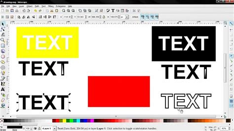
Drawing Text for Cutting/Engraving
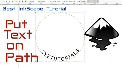
- Use the Text Tool: Create your text using Inkscape's Text tool. The bottom-left corner of your document is typically set as the machine's 0,0 origin.
- Convert to Path: Select the text and convert it to a path using
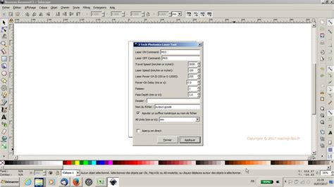
Path > Object to Path(Shift + Ctrl + C). This is essential for the laser to interpret the text's geometry. - Generate G-code: Access the laser tool plugin via
Extensions > Generate G Code > J Tech Photonics Laser Tool(or the equivalent for your installed plugin). - Configure Settings: Fill in the dialog box with appropriate parameters for your material, laser, and desired outcome (cutting, engraving, speed, power, etc.).
- Apply: Click "APPLY" to generate the G-code file. The plugin will typically outline the generated laser path for visualization.
Drawing Other Objects
The same principles apply to drawing other shapes. Use Inkscape's drawing tools (rectangles, ellipses, freehand drawing, etc.) to create your desired objects. Before generating G-code, ensure all objects intended for cutting or engraving are converted to paths.
Drawing Multiple Objects
To process multiple distinct objects within a single G-code file, they must first be grouped and then converted to paths.
- Draw Objects: Create your separate objects.
- Group Objects: Select all objects that should be treated as a single entity for G-code generation and group them (
Ctrl + G). - Convert to Path: With the group selected, convert it to a path.
- Generate G-code: Open the laser tool plugin, configure settings, and apply to generate the G-code.
Importing Pictures or Images for Engraving
Engraving black and white, high-contrast images is a popular application for laser cutters.
- Import Image: Use
File > Importto bring your image into Inkscape. - Trace Bitmap: For raster images, use Inkscape's tracing tools.
Path > Trace Bitmapoffers options like Edge Detection or Brightness Cutoff. Edge detection can help outline shapes, while Brightness Cutoff can create a binary (black and white) image based on luminosity. - Update and Apply: Adjust the settings in the Trace Bitmap dialog and press "OK" to apply.
- Clean Up: Delete the original imported image, leaving the traced vector object.
- Convert to Path: Ensure the traced image is converted to a path (
Path > Object to Path). - Generate G-code: Use the laser tool plugin to generate the G-code for engraving.
Creating G-code for Engraving and Cutting on the Same Drawing
A common requirement is to engrave areas of a design while cutting out its outline. This involves creating separate "objects" for engraving and cutting within Inkscape and processing them sequentially.
- Define Objects: Design your file with distinct elements for engraving and cutting. For example, text to be engraved and a border to be cut.
- Process Engraving Object: Select the object(s) intended for engraving. Convert them to paths (
Path > Object to Path). Open the laser tool plugin, set parameters for engraving (higher speed, lower power), and click "Apply." This generates an engraving G-code file. - Process Cutting Object: Deselect the engraving objects and select the object(s) intended for cutting (e.g., the outline). Convert them to paths. Open the laser tool plugin again, but this time configure parameters for cutting (lower speed, potentially multiple passes, higher power). Crucially, change the filename or use the "Add Numeric Suffix" option to avoid overwriting the engraving file. Click "Apply" to generate the cutting G-code file.
This process results in at least two separate G-code files. These can be run sequentially on the laser cutter, provided the workpiece is not moved between operations. Alternatively, the two G-code files can be manually combined into a single file using a text editor.
Important Design Conventions for Laser Cutting:
- Cutting Lines: To be interpreted as cuts, lines should typically be RGB red with a stroke weight of 0.01mm and no fill.
- Engraving Lines/Fills: Vector engraving can be achieved by using RGB blue lines with a 0.01mm stroke weight and no fill, or more commonly, by filling shapes with shades of grey. White is not engraved, light grey results in shallow engraving, and black results in the densest engraving. For raster engraving, shades of grey within a fill dictate the engraving depth.
- Color Images: Color images are usually converted to greyscale via dithering for engraving, with density controlled by shades of grey, similar to fills.
- Rasterized Images: When rasterizing images for engraving, a resolution of 150 DPI is often recommended to maintain crispness.
Handling Double Lines and Shared Sides
A common issue in vector designs for laser cutting is the presence of double lines or shapes with shared sides, which can lead to inefficient cutting, increased burn marks, and potential damage to the cutting table.
- Double Lines: These appear darker than single lines and can significantly increase cutting time and cost. If detected, one of the overlapping lines should be deleted.
- Shared Sides: When two shapes share a common edge (e.g., two adjacent rectangles), the shared line needs to be "broken" to ensure it's treated as a single path for cutting.
- Select one of the objects.
- Use the "Edit paths by node" tool.
- Select a corner node on the shared line.
- Click the "Break path at selected nodes" button.
- Repeat for the other corner of the shared line.
- The shared line can now be selected and deleted or modified as needed. The nodes on the line will typically show a yellow glow when selected.
Design Considerations for Material and Aesthetics
When designing for laser cutting, several factors influence the final outcome, including the choice of font, the material being cut, and the desired aesthetic.
Font Selection for Laser Cutting
The choice of font is crucial. Some fonts are better suited for laser cutting than others. Fonts with thicker strokes are generally more robust and less prone to breaking, especially when used for smaller text or intricate designs. Fonts with sharp serifs or very thin elements can be challenging to cut cleanly and may require careful handling during the design and bridging phases. While this article focuses on the technical aspects of preparing text, exploring resources for recommended laser-cutting fonts can significantly improve project success.
Material Properties and Design Limitations
The material being cut dictates many design constraints. Different materials (wood, acrylic, metal, fabric) have varying laser cutting characteristics, including melting points, vaporization rates, and susceptibility to heat.
- Minimum Geometry: As mentioned with bridging, there's a minimum size for features that the laser can reliably cut. Very small holes or thin connections may not cut cleanly or may break during removal.
- Kerf: The laser beam removes a small amount of material as it cuts, known as the "kerf." This width needs to be accounted for in designs where precise fits are required. For example, if you need two parts to fit snugly together, you might need to slightly enlarge the opening in one part to compensate for the kerf. The kerf width varies depending on the laser power, material, and cutting speed.
- Engraving Depth and Control: For engraving, the depth is controlled by the laser's power, speed, and the dwell time. In Inkscape, using shades of grey for fills is an effective way to control engraving depth, with darker shades resulting in deeper engravings.
Aesthetic Considerations
While technical requirements are paramount, aesthetic considerations should not be overlooked.
- Balance: Ensure that bridging elements do not detract from the overall visual appeal. Well-designed bridges can be subtle or even incorporated as design features.
- Readability: For signage or text-based designs, maintaining readability is key. Extremely stylized fonts or complex bridging can sometimes hinder legibility.
- Complexity: Overly complex designs with intricate details or very small features can be challenging to cut and may require multiple passes or slower speeds, increasing production time and cost.
Conclusion: Preparing for Your Next Laser Cutting Project
Mastering Inkscape for laser engraving and cutting projects involves understanding the core principles of vector design, the specific requirements of laser cutters, and the functionality of G-code generation plugins. By converting text and shapes to paths, appropriately bridging internal cuts, and configuring G-code settings with attention to material properties and desired outcomes, you can effectively translate your creative visions into physical objects. The accessibility of Inkscape, combined with its robust feature set and the availability of powerful plugins, makes it an indispensable tool for anyone venturing into the world of custom laser-cut and engraved creations. Remember to consult your laser cutter's manual and experiment with settings to achieve the best results for your specific materials and projects.